Sending the wrong file format to a manufacturer is one of the most common — and most avoidable — causes of quoting delays, machining errors, and rejected orders. Here is exactly what each format contains, where it belongs, and what to send for every situation.
You have finished your CAD model. You are ready to send it out for manufacturing, 3D printing, or a quote. The manufacturer asks for the file — and suddenly you are staring at an export menu with fifteen format options and no clear guidance on which one to pick.
STEP, IGES, STL, OBJ, 3MF, Parasolid, DXF — they are all described as CAD formats, they all export from the same software, and they all produce files that open on screen without obvious errors. But they are fundamentally different types of files, and sending the wrong one causes real problems: quotes that come back wrong because the geometry was interpreted incorrectly, prints that fail because the slicer could not process the mesh, and machining errors because the tolerance data was lost in the conversion.
This guide explains what each of the three most important formats actually contains, what each one is designed for, and gives you a clear decision framework for every manufacturing scenario you are likely to encounter.
Why the File Format You Send Actually Matters
The format is not just a container. Different 3D file formats represent geometry in fundamentally different ways, carry different types of information, and have different levels of precision. What you send determines what the manufacturer or printer can actually do with your file.
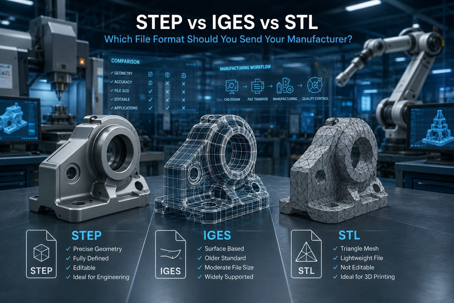
A STEP file contains precise mathematical descriptions of surfaces and solids — exact curves, exact surfaces, exact topology. A manufacturer's CAM software can read this and generate toolpaths from it with full geometric fidelity.
An STL file contains no mathematical surfaces at all. It represents geometry as a collection of flat triangles — a mesh that approximates the surface of the solid. The more triangles, the closer the approximation. But it is always an approximation, and for manufacturing purposes it means tolerances cannot be embedded in the file and curved surfaces are never truly smooth.
Sending an STL file to a CNC machinist is like sending a photograph of a blueprint instead of the blueprint itself. The machinist can see roughly what you want, but the information needed to machine it accurately is not there.
Understanding this distinction — and applying it correctly — is the difference between a file that gets machined on the first pass and one that generates a list of questions and delays before work can even begin.
STEP — The Manufacturing Standard
STEP .stp / .step
Standard for the Exchange of Product Data — the universal format for manufacturing and engineering
What STEP Is
STEP stands for Standard for the Exchange of Product Data. It is an ISO standard — ISO 10303 — developed specifically to enable the exchange of complete, precise product data between different CAD, CAM, and engineering systems. It is the closest thing the manufacturing industry has to a universal language.
A STEP file contains true mathematical geometry. Curved surfaces are stored as exact mathematical equations — NURBS curves and B-spline surfaces — not as triangle approximations. This means that when a CNC machinist's CAM software reads a STEP file, it is working from the exact geometry you designed, not a faceted approximation of it.
Beyond raw geometry, STEP can carry additional engineering data depending on the version. STEP AP214 is the standard version used by most CAD software — it carries geometry, topology, and basic product structure. STEP AP242 is the more recent version that adds geometric dimensioning and tolerancing data, meaning tolerances you have applied in your CAD model can be embedded in the STEP file itself and read by downstream inspection and manufacturing systems.
What STEP Contains
• Exact mathematical geometry — NURBS surfaces, B-splines, precise curves
• Complete solid body topology — the relationships between faces, edges, and vertices
• Assembly structure — multiple parts and their positional relationships
• Material and colour assignments in most CAD software implementations
• Tolerance data in STEP AP242 format
• Product metadata — part names, revision numbers, author information
Where STEP Belongs
STEP is the correct format for virtually every manufacturing application. If you are sending a file to a CNC machinist, use STEP. If you are sending to a vacuum casting service, use STEP. If you are obtaining manufacturing quotes from multiple suppliers, use STEP. If you are providing files to a supplier who will be programming their own CAM software, use STEP.
STEP is also the right format when you want to send editable geometry that the manufacturer may need to reference or check dimensions from — because a STEP file preserves all geometric information with full fidelity.
Where STEP Does Not Work Well
STEP is not ideal for 3D printing slicers, which are designed to work with mesh formats rather than solid geometry. Most slicers can import STEP files, but they immediately convert them to an internal mesh representation — which means you lose nothing by sending STL or 3MF directly for printing purposes.
STEP is also not the format for 2D laser cutting or sheet metal DXF-based workflows, which have their own format requirements covered later in this post.
✅ When to Send STEP
CNC machining — always
Vacuum casting — always
Injection moulding quoting — always
Any manufacturing process where dimensional accuracy matters
When sending to a supplier who will program CNC or CAM from your file
When sending files between different CAD software platforms
When tolerance data needs to travel with the geometry (use AP242)
IGES — The Legacy Format Still in Active Use
IGES .igs / .iges
Initial Graphics Exchange Specification — older standard, still requested by some manufacturers and aerospace suppliers
What IGES Is
IGES stands for Initial Graphics Exchange Specification. It was developed in the late 1970s as one of the first standards for exchanging CAD data between different software systems — decades before STEP existed. For a long time it was the dominant neutral exchange format in manufacturing, and it remains widely supported today across almost every CAD and CAM platform.
Like STEP, IGES stores mathematical geometry — curves and surfaces represented as equations rather than triangles. A manufacturer receiving an IGES file gets precise surface data that their CAM software can work with accurately.
The practical differences between IGES and STEP are largely historical. IGES predates many of the data structures that STEP was designed to handle, so it is less capable at representing complex assembly structures, and it does not support tolerance data in the way that STEP AP242 does. It also has some known quirks around how different CAD systems interpret its surface data, which occasionally produces translation artefacts that STEP handles more cleanly.
What IGES Contains
• Mathematical surface and curve geometry — similar precision level to STEP
• Solid body geometry in most modern implementations
• Basic assembly structure, though less robustly than STEP
• Colour and layer information
• No native support for GD&T or tolerance data
Where IGES Is Still Requested
IGES remains in active use in several specific contexts. Aerospace and defence supply chains frequently specify IGES as a required delivery format alongside or instead of STEP, because many legacy inspection and manufacturing systems in those industries were built around IGES and have not been updated. Some older CAM software installations at established machining shops still prefer IGES over STEP for compatibility reasons.
If a manufacturer explicitly requests IGES, send IGES. If they ask for either format, send STEP. If they have not specified a preference and are a modern shop, STEP is the better default.
The Honest Assessment of IGES Today
IGES is a format in gradual decline. Every new manufacturing software system supports STEP as its primary neutral format, and STEP AP242 handles everything IGES does while doing significantly more. For new workflows and new supplier relationships, STEP is the right choice. IGES is a format you use when a specific supplier or system requires it — not because it is inherently better for any current application.
✅ When to Send IGES
When a manufacturer or supplier explicitly requests it
Aerospace and defence supply chains that specify IGES as a standard
When working with legacy CAM systems confirmed to prefer IGES
As a secondary format alongside STEP if requested
Never as a first choice when STEP is also acceptable
STL — The 3D Printing Standard
STL .stl
Stereolithography file — the universal mesh format for 3D printing, not suitable for manufacturing
What STL Is
STL stands for Stereolithography, named after the first commercial 3D printing process it was developed to support in the 1980s. An STL file represents geometry as a collection of triangular faces — a mesh that approximates the surface of a 3D object. There are no mathematical curves, no true surfaces, no parametric relationships. Just triangles.
The approximation quality of an STL depends on how many triangles are used. A coarse STL file of a sphere looks faceted — you can see the flat triangular faces clearly. A fine STL file of the same sphere looks smooth, because the triangles are small enough that the eye cannot resolve individual faces. But even the finest STL is still an approximation. A truly smooth curve can only be represented exactly by a mathematical equation, which STL does not support.
STL files also contain no unit information by default. A file that represents a part designed in millimetres is geometrically identical to the same file interpreted in inches — the numbers are the same, only the physical interpretation differs. If you send an STL file and the manufacturer or slicer is set to a different unit, the part will be the wrong size.
What STL Contains
• A list of triangular faces, each defined by three vertex coordinates and a normal vector
• No curve or surface mathematics — all geometry is approximated by flat triangles
• No tolerance or engineering data
• No colour, material, or layer information in the basic format
• No unit specification — units must be communicated separately
• No assembly structure — STL is always a single mesh body
Where STL Belongs
STL is the native format of 3D printing, and it is the right format to send any FDM, SLA, SLS, or other additive manufacturing service when you are sending a file for direct printing. Every 3D printing slicer — PrusaSlicer, Chitubox, Cura, Simplify3D — reads STL natively and processes it without conversion. Online 3D printing services typically accept STL as their primary upload format.
For 3D printing of visual models, prototypes, and functional parts where the approximation quality of STL is sufficient, it is perfectly adequate. The key is to export at a resolution fine enough that the faceting is not visible or functionally significant. As a general rule, export STL at a chord height or deviation tolerance of 0.01 mm or finer for any part where surface smoothness matters.
Where STL Should Not Be Used
STL should not be sent to a CNC machinist. The absence of true surface mathematics means the machinist's CAM software must reconstruct surfaces from the triangle mesh — a process that introduces approximation errors and cannot reliably recover the original design intent. Many CAM systems will simply reject an STL file or flag it as unsuitable for precision machining.
STL should not be used when dimensional accuracy is critical. The triangle approximation means that a curved feature specified to a tight tolerance in your CAD model may not be represented accurately enough in the STL to hold that tolerance. STEP preserves the exact geometry and the tolerance data; STL discards both.
STL should not be used for injection moulding or vacuum casting files sent to a toolmaker. These applications require precise surface data to generate accurate toolpaths and mould cavities.
✅ When to Send STL
FDM, SLA, SLS, and all other 3D printing applications — it is the standard
Online 3D print services — STL is the most universally accepted format
Visual and cosmetic prototypes where surface approximation is acceptable
When a manufacturer or service explicitly requests STL
Never for CNC machining, injection moulding, or vacuum casting
Never when dimensional tolerances tighter than plus or minus 0.1 mm are required
Other Formats Worth Knowing
STEP, IGES, and STL cover the majority of manufacturing scenarios, but there are several other formats you will encounter in specific contexts.
3MF — The Improved 3D Printing Format
3MF was developed by the 3MF Consortium — a group that includes Microsoft, Autodesk, Ultimaker, and other major industry players — as a modern replacement for STL specifically for 3D printing. It addresses most of the limitations of STL: it includes unit specification, so the physical size is unambiguous, it supports colour and multi-material assignments, it can embed texture maps, and it uses a more efficient data structure that produces smaller file sizes.
If your 3D printing service or slicer supports 3MF — and most modern ones do — it is a better choice than STL for colour models, multi-material prints, or any situation where you want the unit specification embedded in the file. For single-colour structural prints, STL and 3MF are functionally equivalent.
OBJ — Visualisation and Game Assets
OBJ is a mesh format primarily used in visualisation, rendering, and game development. Like STL, it represents geometry as a mesh of polygons. Unlike STL, it supports colour, material, and texture map assignments, making it the standard format for assets that need appearance data alongside geometry. OBJ is not a manufacturing format and should not be sent to any fabrication process that requires dimensional accuracy.
DXF and DWG — 2D and Sheet Metal
DXF and DWG are 2D formats associated with AutoCAD. They are the standard for 2D laser cutting, sheet metal flat patterns, and technical drawings. If you are sending a part for laser cutting or waterjet cutting, the manufacturer typically needs a 2D DXF file of the flat profile, not a 3D solid file. Some sheet metal CAM software can derive this automatically from a STEP file of the folded part, but many shops prefer to receive the DXF directly.
Native CAD Formats — SolidWorks, Fusion 360, Parasolid
Native formats from specific CAD software — SolidWorks .sldprt, Fusion 360 .f3d, Parasolid .x_t, Catia .CATpart — carry the most complete information about a design, including full parametric history, feature tree, and all engineering data. Some manufacturers request native files when they need to be able to modify the geometry or work directly within your design system. The downside is that the recipient must have the same software or a compatible version to open and work with the file correctly. For most manufacturing purposes, STEP is preferable because it does not create a software dependency.
The Simple Decision Guide: Which Format to Send
Here is the practical decision framework for the most common scenarios, written as clearly as possible.
For CNC Machining
Always send STEP. No exceptions. STEP gives the machinist's CAM software exact geometry, preserves all surface mathematics, and allows accurate toolpath generation. If the machinist requests IGES specifically, send IGES. If they have not specified a preference, send STEP. Never send STL for CNC work.
For 3D Printing — FDM, SLA, SLS
Send STL or 3MF. STL is universally supported and the safest choice if you are unsure what the service accepts. 3MF is preferable if you have colour, multi-material, or unit clarity requirements. Never send STEP to a 3D print service expecting them to print from it directly — most will convert it to a mesh internally, which adds an unnecessary step and occasionally introduces conversion issues.
For Injection Moulding and Vacuum Casting
Always send STEP. These processes require precise surface geometry for toolpath generation and mould design. IGES is acceptable if specifically requested. Never send STL for tooled manufacturing processes.
For Laser Cutting and Sheet Metal Flat Cutting
Send DXF for the 2D flat profile. If the manufacturer also wants a 3D reference for the folded or formed part, include a STEP file alongside the DXF. Do not send only a 3D file to a 2D cutting process — most operators work from flat profiles and do not want to derive them from a 3D solid.
For Getting a Manufacturing Quote
Send STEP for all subtractive and tooled processes. The manufacturer needs enough geometric information to assess complexity, setups, and special features. An STL file does not give them this — tolerances and surface mathematics are absent, so they cannot assess machining requirements accurately. Always send STEP for quotes, along with a 2D PDF drawing if you have one.
For Sending Files Between CAD Software
Send STEP. It is the most reliable neutral format for carrying geometry between different CAD platforms without loss of surface accuracy. IGES is an alternative but STEP handles more complex geometry more reliably. Native formats are better if both parties use the same software version.
For Game Engines and Visualisation
Send OBJ or FBX. These are the standard formats for real-time 3D applications and rendering software. STL works for basic mesh import but does not carry material or texture data. Neither STEP nor IGES is appropriate for game engine or visualisation use — they are engineering formats, not asset formats.
📋 Quick Reference — Format by Application
CNC Machining → STEP (.stp) — always
3D Printing (FDM / SLA / SLS) → STL (.stl) or 3MF (.3mf)
Injection Moulding / Vacuum Casting → STEP (.stp)
Laser Cutting / Sheet Metal → DXF (.dxf) for flat profile + STEP for reference
Manufacturing Quotes → STEP (.stp) + PDF drawing
Between CAD Software → STEP (.stp)
Game Engine / Renders → OBJ or FBX
Legacy Aerospace Suppliers → IGES (.igs) if specified
How to Export These Formats Correctly
Choosing the right format is half the work. Exporting it correctly is the other half. Poor export settings produce files that are technically the right format but carry the wrong geometry — STL files with too-coarse faceting, STEP files with missing faces from incorrect export options, or files in the wrong units.
Exporting STEP from SolidWorks
Go to File, then Save As, and select STEP AP214 or STEP AP242 from the format list. AP214 is fine for most manufacturing purposes. AP242 is recommended if you want to embed GD&T data. In the STEP export options dialog, ensure that solid bodies are included and that the export scope covers all components if you are exporting an assembly. Check that units are set to your working unit before export.
Exporting STEP from Fusion 360
Go to File, then Export, and select STEP from the format dropdown. Fusion 360 exports a clean STEP file with no additional configuration needed for most cases. Do not use the right-click export from the browser panel, as this can occasionally miss geometry states in complex models. Use File, then Export from the main menu.
Exporting STL from Any CAD Software
The most important STL export setting is the chord tolerance or deviation value — this controls how finely the mesh approximates curved surfaces. A value of 0.01 mm is a safe general setting for manufacturing and fine prototyping. Values higher than 0.1 mm will produce visible faceting on curved surfaces at normal part sizes. Ensure the unit setting matches your working units in the CAD file — a mismatch here produces a part that is either twenty-five times too large or too small when the file is interpreted in the wrong unit.
Checking Your File Before Sending
Before sending any file to a manufacturer, open it in a viewer — Autodesk Viewer, GrabCAD Workbench, or eDrawings are all free — and visually confirm that the geometry looks correct. For STL files specifically, import into PrusaSlicer or Meshmixer and run a quick mesh check to confirm the file is watertight and free of errors. A thirty-second file check before sending can prevent days of back-and-forth after a manufacturer receives a broken file.
What File Package Solidus 3D Modeling Delivers
When Solidus 3D Modeling delivers a completed CAD model, the standard deliverable package is built around the intended manufacturing process from the outset — not a single file that the client then has to convert.
For parts intended for CNC machining or tooled manufacturing, we deliver a STEP file as the primary geometry, a 2D engineering drawing as a PDF for tolerance and inspection reference, and the native CAD file in SolidWorks or Fusion 360 format for future revisions. For parts intended for 3D printing, we deliver both a STEP file for reference and an STL or 3MF optimised for the specific printing technology requested. For designs that will go through multiple processes — prototyped by 3D printing and then manufactured by CNC or injection moulding — we include all relevant formats in a single handover package.
Every file is checked before delivery. STEP files are opened and verified in a neutral viewer. STL files are run through a mesh validation check. File units are confirmed against the drawing. This is standard practice, not an optional extra, because a file that fails at the manufacturer's end costs everyone time regardless of where the error originated.
📩 Need a File in the Right Format for Your Manufacturer?
Send your brief, sketch, or reference file to info@solidus3dmodeling.com
Or use the quote form at solidus3dmodeling.com/instant-quote.php
Specify your manufacturing process and we will deliver the correct format from the start
All files received and delivered under NDA — your IP is protected
Frequently Asked Questions
Can I send an STL file to a CNC machinist?
Technically you can, but you should not. An STL file contains no mathematical surface data — only a triangular mesh approximation of the geometry. A CNC machinist's CAM software needs precise surface data to generate accurate toolpaths. Sending STL for CNC work produces imprecise toolpaths, causes the machinist to ask questions your file cannot answer, and often results in a rejected file or an inaccurate quote. Always send STEP for CNC machining.
What is the difference between STEP AP214 and STEP AP242?
Both are versions of the STEP standard. AP214 is the established version supported by virtually all CAD and CAM software — it carries geometry, topology, and basic product data. AP242 is the more recent version that adds support for geometric dimensioning and tolerancing data, meaning tolerance callouts from your CAD model can be embedded in and read from the STEP file itself. For most manufacturing purposes, AP214 is sufficient. If you need to carry GD&T data in the file, use AP242.
Is STEP or IGES better for manufacturing?
STEP is better in almost every situation. It is a newer standard, handles more complex geometry more reliably, supports tolerance data in the AP242 version, and is the primary neutral format in modern CAM and engineering software. IGES is still widely supported and perfectly functional, but should be used when a specific supplier or system requests it rather than as a general default.
Why is my STL file the wrong size when the manufacturer opens it?
STL files do not contain a unit specification. If your CAD software exported the file in millimetres and the manufacturer's software opened it in inches — or vice versa — the part will be either twenty-five times too large or too small. Always confirm units with your manufacturer when sending STL files, and consider switching to 3MF format, which embeds unit information directly in the file.
Can I send a native SolidWorks or Fusion 360 file to a manufacturer?
You can, if the manufacturer uses the same software at a compatible version. The advantage is that native files carry full parametric history and all feature data. The disadvantage is the software dependency — if the manufacturer uses a different CAD system or a different version, they may not be able to open the file correctly. STEP is the safer default for cross-platform file exchange because it requires no specific software to read accurately.
What file format should I use for a laser cutting order?
For laser cutting of flat profiles, send DXF. This is the standard 2D format for laser and waterjet cutting services. Ensure your DXF is exported at the correct scale and that all cut lines are on a single layer. If the part is a folded sheet metal component, include a 3D STEP file alongside the DXF as a reference for the folded form.
Does file format affect the price of my manufacturing quote?
Indirectly, yes. A STEP file gives a machinist all the geometric information they need to assess your part accurately and generate an informed quote. An STL file requires the machinist to make assumptions about surface quality and tolerances that the file cannot confirm, which typically results in either a higher quote to cover uncertainty or follow-up questions that delay the response. Sending the right format from the start results in faster, more accurate quotes.
No replies yet
Start the discussion
Be the first to ask a follow-up question or add practical insight about this topic.